Home /
Expert Answers /
Other /
in-the-test-set-up-shown-in-the-figure-below-two-different-granular-soils-are-placed-in-the-permeame
(Answered): In the test set-up shown in the figure below, two different granular soils are placed in the permea ...
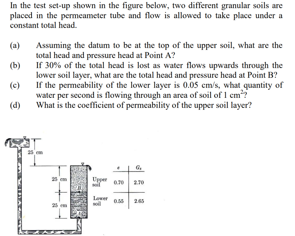
In the test set-up shown in the figure below, two different granular soils are placed in the permeameter tube and flow is allowed to take place under a constant total head (a)Assuming the datum to be at the top of the upper soil, what are the (b) If 30% of the total head is lost as water flows upwards through the (c) If the permeability of the lower layer is 0.05 cm/s, what quantity of (d)What is the coefficient of permeability of the upper soil layer? total head and pressure head at Point A? lower soil layer, what are the total head and pressure head at Point B? water per second is flowing through an area of soil of 1 cm*? 25 cm 25 cm Upper 0.702.70 soil Lower 0.55 2.65 soil 25 cm