Home /
Expert Answers /
Other /
problem-linear-feedback-shift-register-1-we-have-seen-the-3-bit-lfsr-circuit-from-lecture-11-the-fol
(Answered): Problem: Linear Feedback Shift Register 1. We have seen the 3-bit LFSR circuit from lecture 11. The ...
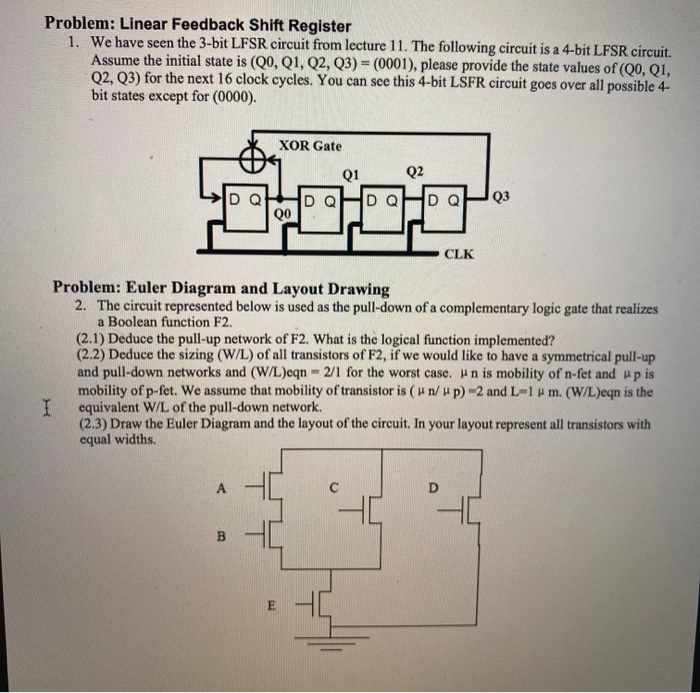
Problem: Linear Feedback Shift Register 1. We have seen the 3-bit LFSR circuit from lecture 11. The following circuit is a 4-bit LFSR circuit. Assume the initial state is (Q0, Q1, Q2, Q3) = (0001), please provide the state values of (Q0, Q1, Q2, Q3) for the next 16 clock cycles. You can see this 4-bit LSFR circuit goes over all possible 4- bit states except for (0000). XOR Gate Q1 Q2 Q DQ Q3 QO CLK Problem: Euler Diagram and Layout Drawing 2. The circuit represented below is used as the pull-down of a complementary logic gate that realizes a Boolean function F2. (2.1) Deduce the pull-up network of F2. What is the logical function implemented? (2.2) Deduce the sizing (W/L) of all transistors of F2, if we would like to have a symmetrical pull-up and pull-down networks and (W/L)eqn - 2/1 for the worst case. Hn is mobility of n-fet and up is mobility of p-fet. We assume that mobility of transistor is (H n/up) -2 and L=14 m. (W/L)eqn is the I equivalent W/L of the pull-down network (2.3) Draw the Euler Diagram and the layout of the circuit. In your layout represent all transistors with equal widths. A B E